What's on this page
Introduction to exceptions and interrupts in Mips
Mandatory assignment
Learning outcomes
In this assignment you will study the differences between exceptions and interrupts and how to implement a simple exception and interrupt handler. You will also study how both exceptions and interrupts causes a transfer of control from user mode to kernel mode and back to user mode after the exception or interrupt have been handled by the kernel.
Method
To study exception and interrupt handling you will load a small Mips
assembly program into the Mips simulator Mars.
simulator MARS. The program will deliberately trigger the following exceptions:
- Arithmetic overflow.
- Address error.
- Trap.
By single-stepping the program you will examine in detail what actions are taken in order to handle each exception. You will also study keyboard interrupts and how this can be used make the CPU do something different while waiting for user input. To get a fully working system you must add or change the provided code at a few places.
Preparations
Before you continue you must perform the following preparations.
Clone repository
If you haven’t done so already, you must clone the module-1 repository.
Start Mars
Log in to the department Linux system. From the Applications menu you find Mars under Programming.

Mars should now start and you should see something similar to this.

Open file
Open the file module-1/mandatory/exceptions-and-interrupts.s in Mars.
Study the source code
Study the assembly source code of the loaded program in the built in editor pane.
A brief overview
Read the code with the intention of getting an overview of the overall structures
structured. Focus on labels and jumps to labels. Focus on the difference
between the user text segment (.text) and kernel text segment (.ktext). You will study the details
later.
Don't edit the source
You should not edit the source code at this stage.
User level code
After an introductory comment you find the .text assembler directive followed by
the label main which is the entry point of the user mode program. In main:
- First and arithmetic overflow exception is triggered by adding
1to the largest positive 32 bit two’s complement value0x7fffffff. - Next an address error exception is triggered by trying to load a value from an invalid memory address (address 0).
- Finally, a trap exception is triggered using the
teqi(Trap EQual Immediate) instruction.
At the end of main the program enters an infinite loop incrementing a counter
(register $s0).
Kernel level code
The assembler directive .ktext 0x80000180 instructs the assembler to place the
generated machine instructions in the kernel text segment starting at memory
address 0x80000180. Here the label __kernel_entry_point marks the entry point
of the exception handler (kernel). Note that this label is not needed but simply
included to make it obvious to a human reader where the exception handler
starts.
When an exception or interrupt occurs, the address of the program counter of the currently executing program is automatically saved to the EPC register in coprocessor 0 and control is transferred from user mode to kernel mode.
When entering the kernel, the kernel must determine whether this due to an an exception or an interrupt.
- First the kernel loads the value of the cause register from coprocessor 0.
- Next the exception code is extracted from the cause register. The exception code will be zero for an interrupt and non-zero for an exception.
- Using a conditional branch execution will continue at the label
__interruptfor an interrupt and at label__excepetionfor an exception.
For an exception, the exception code must be further examined to distinguish between different exceptions.. For interrupts the pending interrupt bits in the cause register is used to distinguish between different interrupts. At the end of the kernel execution is resumed in user mode at the address saved in the EPC register in coprocessor 0.
Adjust the run speed
Adjust the simulated run speed to 25 inst/sec or lower.

First test run
Before you continue, clear both the Mars Messages and Run I/O.
Assemble the file by clicking on the icon with the screwdriver and wrench.
You should see something similar to the following in the Mars Messages display pane.
Assemble: assembling /path/to/file/exceptions-and-interrupts.s

Assemble: operation completed successfully.
Click on the play icon to run the program to completion.
In the Run I/O display window you should see the following output.
===>      Arithmetic overflow       <===

===>      Arithmetic overflow       <===

===>      Arithmetic overflow       <===

===>      Arithmetic overflow       <===
What is going on?
Spend some time to see if you can come up with an explanation as to why the same error message printed over and over again.
Click on the stop button to stop the simulation.
Before you continue, clear both the Mars Messages and Run I/O.
Pseudo instructions
In the Execute pain the source instructions are shown in the Source column and
the actual instructions produced by the assembler are shown in the Basic column.
Note that the first source instruction li $s0, 0x7fffffff is a pseudo
instruction that is translated to one lui instruction and one ori instruction,
both using the $at (Assembler Temporary) register.
Arithmetic overflow step by step
It is now time to study the execution in more detail by execute one instruction
at the time using the ![]() button.
button.
Assemble the file.
The largest positive integer
The program starts with storing the largest 32 bit
positive two’s complement
integer in register $s0
using the li (Load Immediate) instuction. This instruction is a pseudo
instruction and translates to one lui instruction and one ori instruction.
- Execute the
li $s0, 0x7fffffffinstruction.
Now, look at the register pane.

Note that register $at (register number 1) have been highlighted and that the value stored in $at
changed from the initial value 0x00000000 to 0x7fff0000 , i.e., the upper
half of the 32 bit value 0x7fffffff is now stored in $at.
Execute the
ori $16, $1, 0x000ffffinstruction, click on the single-step icon.
Now $s0 (register number 4) will be highlighted in the register pane.
Register $s0 now holds the value value 0x7fffffff = [32 bit binary] = 0111 1111
1111 1111 1111 1111 1111 1111, i.e., the largest positive 32 bit
two’s two’s complement
integer.
The program counter
The program counter stores the address of the next instruction to execute.
In the register pane, look at the value of the program counter pc. We see that
pc = 0x00400008. Also note that in the execute pane the instruction at this
address is now highlighted.
The cause register
Look at the cause register in the register pane.

The value in the cause register is currently 0x00000000.
Adding one
We will now try to add one to the integer stored in $s0.
- Execute the
addi $s1, $s0, 1instruction.
The program counter have now jumped from 0x00400008 to 0x80000180, i.e., the
kernel entry point and and the status register is highlighted in the register
pane.

Also note that the cause register changed from 0x00000000 to 0x00000030 and
that EPC have been set to
0x00400008, i.e., been set to the address of the addi.
Step backwards
One great feature of the Mars simulator is the possibility to execute the program backwards.
Undo the execution of
addi $s1, $s0, 1instruction by clicking on the undo button.
Study the values of the program counter, the cause register and the EPC register.
- Execute the
addi $s1, $s0, 1instruction.
Keep undo and redo the execution of the addi instruction and make sure you
understand that this addition causes a transfer of control from user mode to
kernel mode due to an overflow exception and that information about the
exception is stored in the cause register. When the exception happens, the
address of the faulty instruction is automatically saved in the EPC register.
Kernel mode
Execution now continues in the kernel.
Get value in cause register.
The kernel must fetch the value of the cause register from coprocessor 0.
- Execute the
mfc0 $k0, $13instruction.
In the register pane register $k0 should now be highlighted with value
0x00000030 = [binary] = 0000 0000 0000 0000 0000 0000 0011 0000, i.e, a copy of the cause register.
Mask all but the exception code (bits 2 - 6) to zero.
In general, we can’t be sure if other bits that the exception code bits (bits
2 - 6) are set in the cause register. To set all bits but the exception code bits (bits 2 -6) the bitmask
0x0000007C = [binary] = 0000 0000 0000 0000 0000 0000 0111 1100 is used
together with bitwise and.
- Execute the
andi $k1, $k0, 0x00007cinstruction.
In the register pane register $k1 should now have value 0x00000030 = [binary] = 0000 0000 0000 0000 0000 0000 0011 0000,.
Shift to step to the right
To get the value of the exception code we need to shift the value in $k1 two
steps to the right.
- Execute the
srl $k1, $k1, 2instruction.
Register $k1 now hold the exception code = 0x0000000c =
[binary] = 0000 0000 0000 0000 0000 0000 0000 1100 = [decimal] = 12.
Interrupt or exception
The exception code is zero for an interrupt and none zero for all exceptions.
The beqz instruction is now used to jump to the label __interrupt if the
exception code in $k1 is zero, otherwise execution continues on the next instruction.
- Execute the
beqz $k1, __interruptinstruction.
Branch depending on the exception code
The exception code is non zero and the branch is not taken. Next the beq
instruction is used to make a conditional jump to the label
__overflow_exception if the exception code in $k1 is equal to 12.
Execute the pseudo instruction
beq $k1, 12,
__overflow_exception
by clicking twice on step the step forward button. .
Print error message
The branch is taken and execution continues at label __overflow_exception
where a “magic” Mars builtin system call is used to print the error message "===> Arithmetic overflow <===\n\n"
stored in the .kdata segment at label OVERFLOW_EXCEPTION.
Mars magic
Unfortunately the built-in system calls in Mars are implemented as part of the underlying Mips emulator. You cannot single-step the built-in system calls to see how they are implemented. Hence they provide us with a little magic that we cannot study or modify.
Single step four times execute the magic print string system call.
In the Run I/O pane you should now see the following message.
===> Arithmetic overflow <===
Next an unconditional jump to label __resume_from_exception is done.
- Execute the
j __resume_from_exceptioninstruction.
Resume from exception
Execution now continues at the label __resume_from_exception. The value of the
EPC register in now fetch from coprocessor 0.
- Execute the
mfc0 $k0, $14instruction.
Register $k0 now have the value 0x00400008. This is the address that was
automatically stored in EPC when the overflow exception occurred.
Next, this value is stored back to the EPC register in coprocessor 0.
- Execute the
mtc0 $k0, $14instruction.
Transfer control back to user mode
The exception have now been handled by the kernel. The last thing to be done is
to transfer control back to user mode using the eret instruction which makes
and unconditional jump to the address currently stored in EPC.
- Execute the
mtc0 $k0, $14instruction.
Full circle
Execution now continues in user mode at the same instruction that caused the overflow exception in the first place.
- Click on the play button to continue execution..
In the Run I/O display window you should see the following output.
===>      Arithmetic overflow       <===

===>      Arithmetic overflow       <===

===>      Arithmetic overflow       <===

===>      Arithmetic overflow       <===
Click on the stop button to stop the simulation.
Solution
When resuming execution after an exception, we want to resume at the instruction
following the instruction at the address saved in EPC.
Each instruction is four bytes, hence we need to add four to EPC before
executing eret.
- Click on edit to show the source code.
- Press Ctrl-F and search for todo_1.
- Uncomment the following line to add four to the EPC value.
# addi $k0, $k0, 4 # TODO: Uncomment this instruction
Assemble the file.
Before you continue, clear both the Mars Messages and Run I/O.
Click on the play icon to run the program to completion.
In the Run I/O display window you should see the following output.
===>      Arithmetic overflow       <===

===>      Unhandled exception       <===

===>      Unhandled exception       <===
This time there is exactly one arithmetic overflow error message followed two messages about unhandled exceptions.
Click on the stop button to stop the simulation.
Address error and trap exceptions
At label todo_2 you must add code to:
- Branch to label
__trap__exceptionfor exception code 13. - Branch to label __bad_address_exception for exception code 4.
Assemble the file.
Before you continue, clear both the Mars Messages and Run I/O.
Click on the play icon to run the program to completion.
In the Run I/O display window you should see the following output.
===>      Arithmetic overflow       <===

===>   Bad data address exception   <===

===>         Trap exception         <===
Click on the stop button to stop the simulation.
Keyboard interrupts
We will now make the keyboard generate an interrupt for each keypress. In order to do this we must first setup the Mars MMIO simulator.
Enable the Keyboard and display MMIO simulator
To make MARS simulate the memory mapped keyboard receiver (and display transmitter) you must enable this feature.
Open the Keyboard and Display MMIO Simulator window
From the Tools menu, select Keyboard and Display MMIO Simulator.

A new window should now open.

The lower white area of this window is the simulated keyboard.
Connect to MIPS
To make MARS aware of the simulated memory mapped receiver (keyboard), press the Connect to MIPS button in the lower left corner of the Keyboard and Display MMIO Simulator window.
Click on the play icon to run the program to completion.
Infinite loop
The program is now stuck in the infinite loop at label infinite_loop. In the
register pane you should be able to see how the value of register $s0 is
constantly increasing.
Type on the simulated keyboard
Click inside the lower white area of the MMIO simulator window and type a few characters.

Nothing happens, the program is still stuck in the infinite loop.
Click on the stop button to stop the simulation.
Enable keyboard interrupts
At label todo_3 you must add code to enable keyboard interrupts. The simulated keyboard is configured by setting bits in the memory mapped
transmitter control register which appears at address 0xffff0000.

To make the keyboard generate interrupts on keypresses, the bit 1 of receiver control must be set to 1.
Assemble the file.
Click on the play icon to run the program to completion.
Type on the simulated keyboard
Click inside the lower white area of the MMIO simulator window and type a single character.
When you type a character on the simulated keyboard a keyboard interrupt is generated. The interrupt is handled by the kernel.
Adjust the run speed
Adjust the run speed to a slower speed in order to see how the asynchronous keyboard interrupt causes control to be transferred from the user level infinite loop to the kernel where the interrupt is handles and then back to the user level infinite loop.
Click on the stop button to stop the simulation.
Echo
The ASCII value of the pressed key is stored in the memory mapped receiver data register.

At label todo_4 you must add uncomment a number of insructions to load the
ASCII value from receiver control and print it to Run I/O using the Mars builtin
system cal.
Assemble the file.
Click on the label __todo_4 in the labels window.

The instruction at label __todo_4 is now highlighted in the Execute pane. Add
a breakpoint at address.
Click on the play icon to run the program to completion.
Type on the simulated keyboard
Click inside the lower white area of the MMIO simulator window and type a single character.
Execution halted at the breakpoint
When you type a character on the simulated keyboard a keyboard interrupt is generated. The interrupt is handled by the kernel and execution is halted at the breakpoint.
Single step
Continue by single stepping and try to understand how the keyboard interrupt is handled by the kernel and execution resumes in the mode infinite loop.
Once the keyboard interrupt have been handled you should see the pressed character printed to Run I/O.
Repeat
Now you can press play again, press a key on the simulated keyboard and single step after the breakpoint. Repeat a few times to make sure you understand how the keyboard interrupt is handled.
Conclusions
Interrupts and exceptions are used to notify the CPU of events that needs immediate attention during program execution. Exceptions and interrupts are events that alters the normal sequence of instructions executed by a processor.
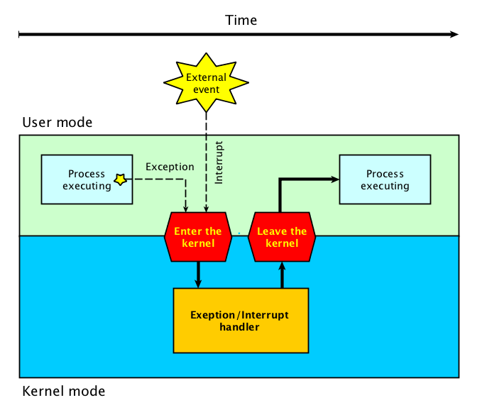
Exceptions are internal and synchronous
- Exceptions are used to handle internal program errors.
- Overflow, division by zero and bad data address are examples of internal errors in a program.
- Another name for exception is trap. A trap (or exception) is a software generated interrupt.
- Exceptions are produced by the CPU control unit while executing instructions and are considered to be synchronous because the control unit issues them only after terminating the execution of an instruction.
Interrupts are external and asynchronous
- Interrupts are used to notify the CPU of external events.
- Interrupts are generated by other hardware devices outside the CPU at arbitrary times with respect to the CPU clock signals and are therefore considered to be asyncronous.
- Key-presses on a keyboard might happen at any time. Even if a program is run multiple times with the same input data, the timing of the key presses will most likely vary.